Application Notes
Remote Sensing
(What are the +SENS and -SENS terminals used for on Acopian power supplies?)

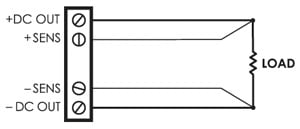
Many Acopian power supplies have +SENS and -SENS terminals (+Sense and -Sense terminals). These terminals may be used for remote sensing of the output voltage and are part of the voltage regulation circuitry. Remote sensing is used to compensate for voltage drops in the output lines. These voltage drops result from the resistance of the lines, and can be significant when the lines are long or the wire gauge is inadequate. If voltage drops in the output voltage lines (which degrade regulation) are not objectionable, local sensing can be used; leave in place the jumpers provided with the power supply on the barrier strip (connecting the +SENS to the +OUT terminal and the -SENS to the -OUT terminal). However, if the best possible regulation at the load is required, then remove the jumpers and use two additional lines to connect the sense terminals to the output lines at the load (the sensing lines can be light gauge wire, since they do not carry output current). This configuration permits the power supply to sense and compensate the voltage actually across the load. Note that remote sensing is capable of compensating only limited wiring drops. The voltage across the load, plus the voltage drops through the wiring, must be within the output voltage range of the supply for the voltage at the load to remain within the load regulation specification.
THE SENSING TERMINALS MUST BE CONNECTED to the output terminals, either at the barrier strip on the power supply or at the load. Failure to have the sense terminals connected will affect the output voltage (usually causing it to be higher than the rating of the supply, and unadjustable), and may result in permanent damage to both the power supply and its load.


 Made In The USA
